About
About This Demonstration
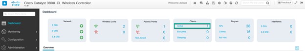
This demo focuses on how to deploy a WLAN within a campus network using Cisco DNA Center. Within this design, a Cisco Catalyst 9800 wireless LAN controller (WLC) is configured and it functions as the enterprise WLC for access points (APs) located on multiple floors, within a specific building of a campus.
Requirements
The table below outlines the requirements for this preconfigured demonstration.
| Required | Details |
|---|---|
|
Endpoint router with Standalone Access Point (CAPWAP in EZVPN1) or Standalone Access Point (CAWAP2) 1- TCP Port 443 required. 2- UDP Port 5246 and 5247 required. |
dCloud Endpoint Router Kit, example (819HWD router), registered and configured for dCloud Note: Internal AP will not work with this demo and should be disabled.
Can be used along with an Endpoint Router (preferred) but can also be used without. See this page for more information Supported wireless access point for the C9800-CL v17.8.1 For more information refer to Release Notes for Cisco Catalyst 9800 Series Wireless Controller, Cisco IOS XE Cupertino 17.8.x |
| Monitoring Workstation | Laptop |
| User Devices |
Tablet, smartphone, or additional laptop Note: For best experience use an iOS device, Android may also work but not as seamless as the iOS devices for BYOD onboarding
Note: BYOD onboarding in this demo is only supported with MAC OSX, Windows, Android and Apple iOS
|
About This Solution
This guide focuses on how to deploy a wireless local area network (WLAN) within a campus network, using Catalyst 9800 Series WLAN controllers (WLCs) with access points (APs) in centralized (local mode) operation, using Cisco DNA Center.
This guide is intended to provide technical guidance to design, deploy, and operate a Cisco WLAN using Cisco DNA Center.
Implementation Flow
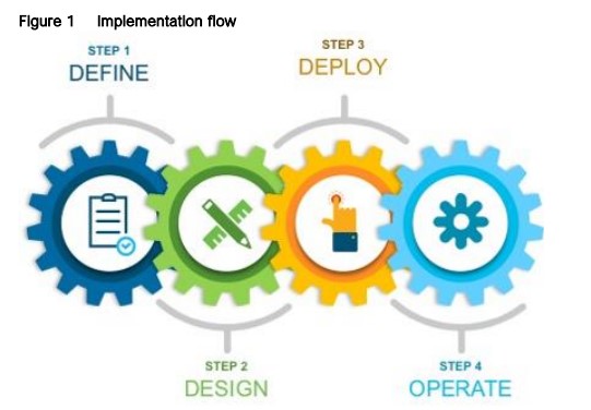
This guide contains four major scenarios:
-
Define the Wireless Network presents an overview of the campus WLAN which will be designed and deployed through Cisco DNA Center. It consists of an enterprise high availability (HA) stateful switch-over (SSO) WLC pair, with APs operating in centralized (local) mode, along with a traditional guest anchor controller.
-
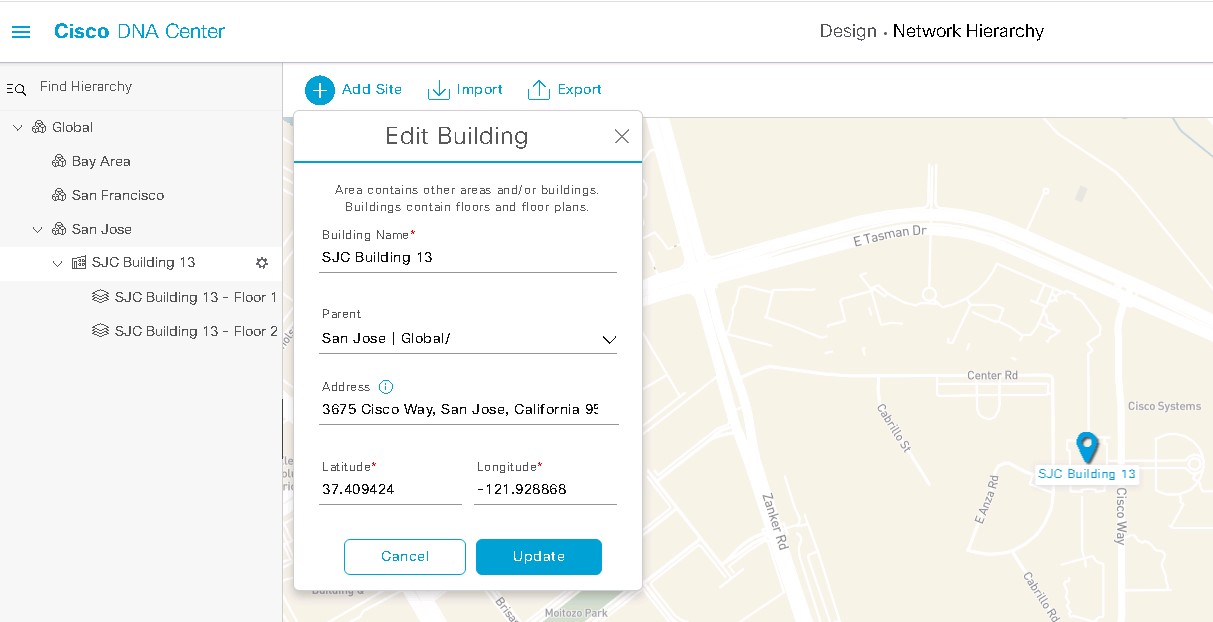
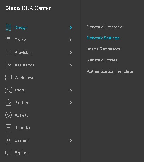
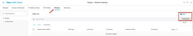
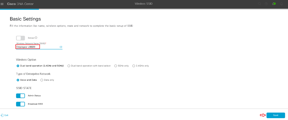
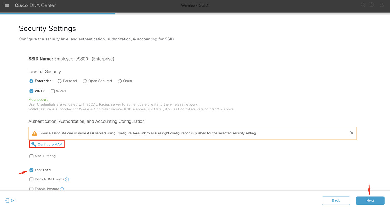
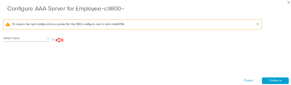
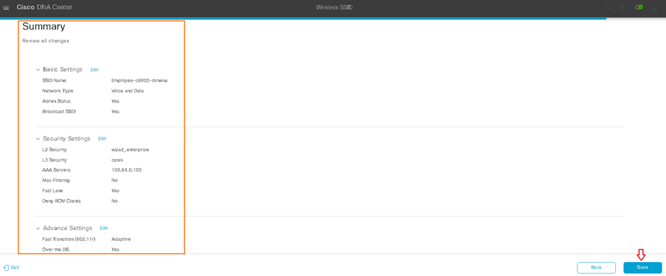
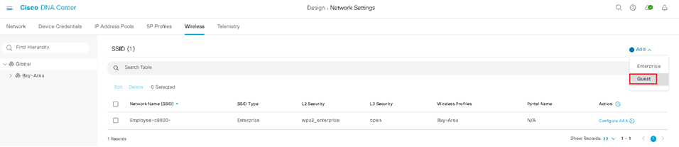
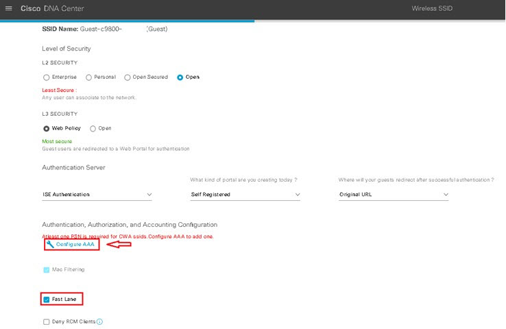
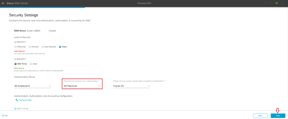
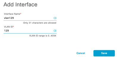
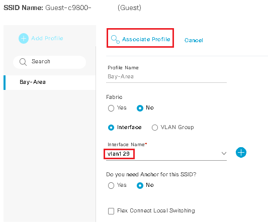
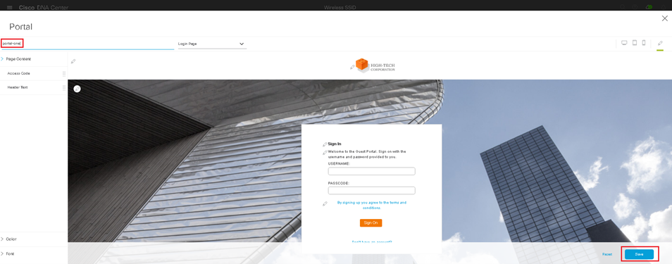
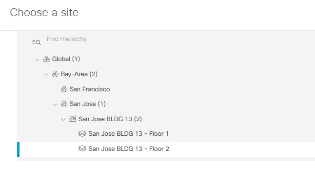
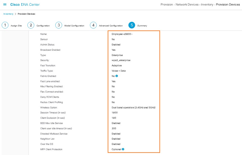
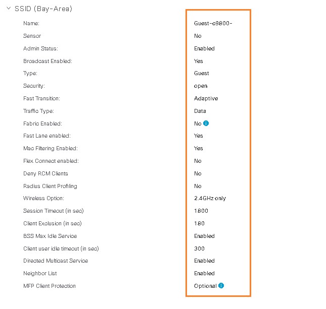
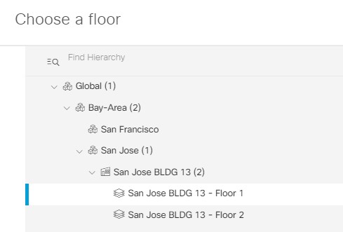
Design the Wireless Network discusses the integration of Cisco DNA Center with Cisco Identity Services Engine (ISE); creation of the site hierarchy including the importing of floor maps within Cisco DNA Center; configuration of various network services necessary for network operations such as AAA, DNS, DHCP, NTP, SNMP, and Syslog servers; and configuration of wireless settings including WLANs/SSIDs, VLANs, and RF profiles for the WLAN deployment. Most of this scenario is already prebuilt and we will simply review it.
-
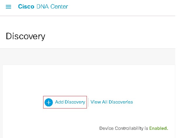
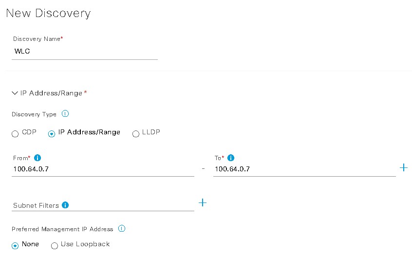
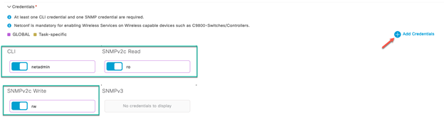
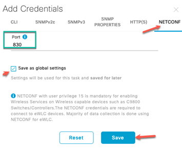
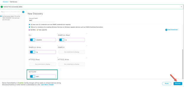
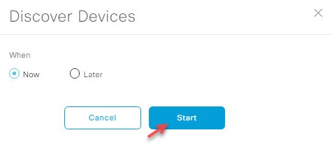
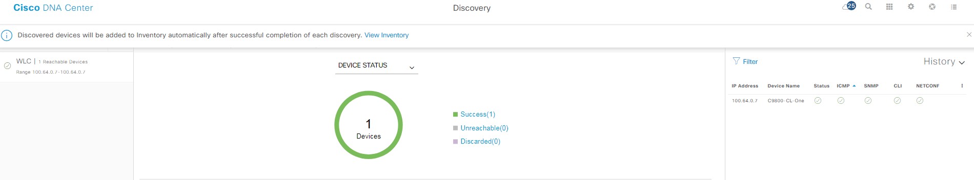
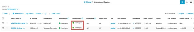
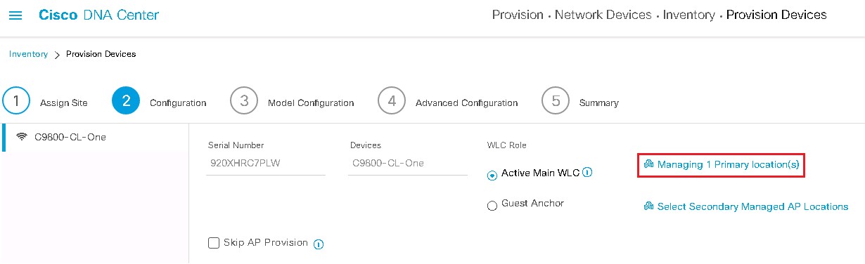
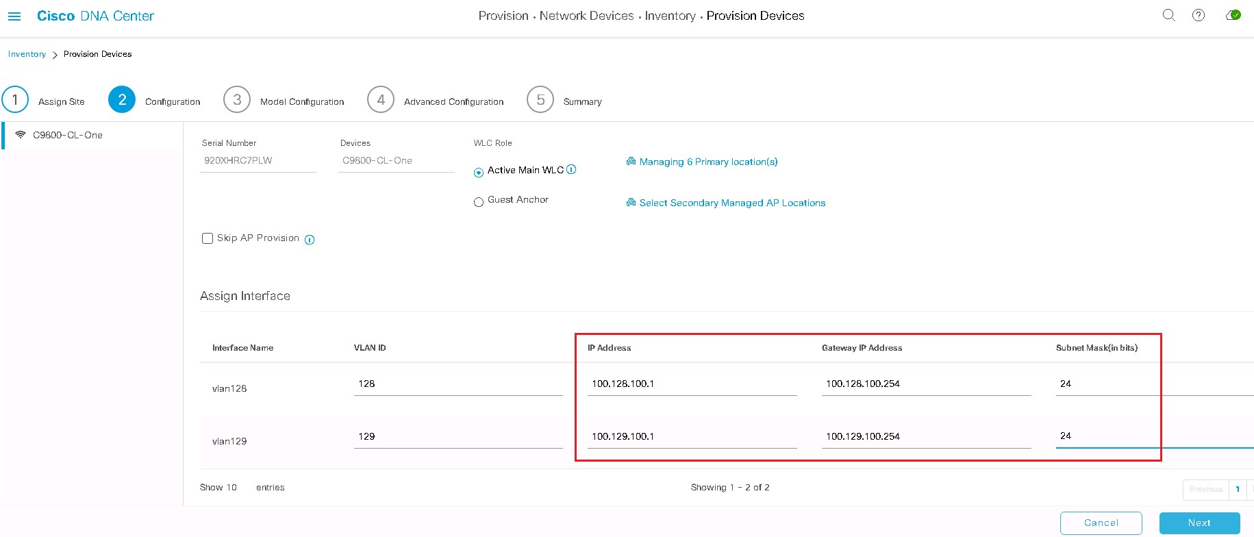
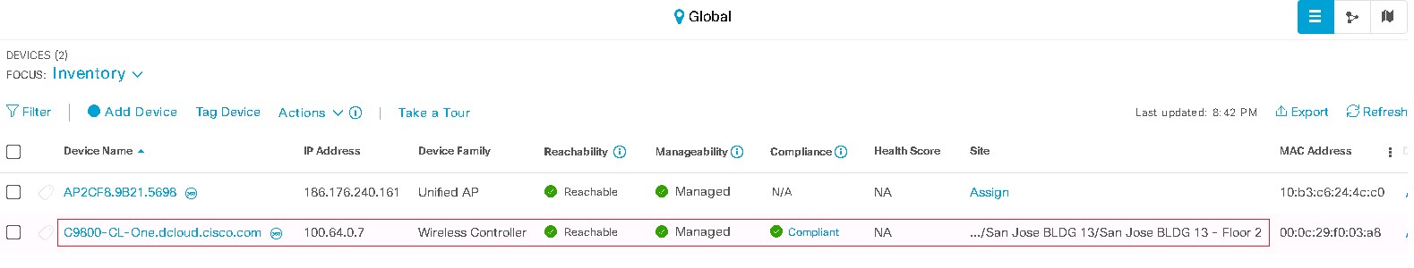
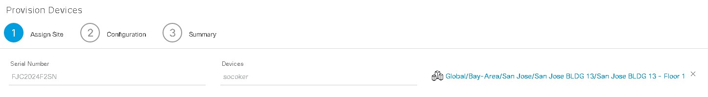
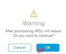
Deploy the Wireless Network discusses discovery of the WLC; managing the software image running on the WLC; configuring HA SSO redundancy on the WLC; provisioning the enterprise and guest WLCs within Cisco DNA Center; joining AP to the enterprise WLC HA SSO pair; provisioning the AP within Cisco DNA Center; and positioning the APs on the floor maps within Cisco DNA Center.
-
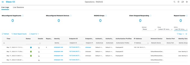
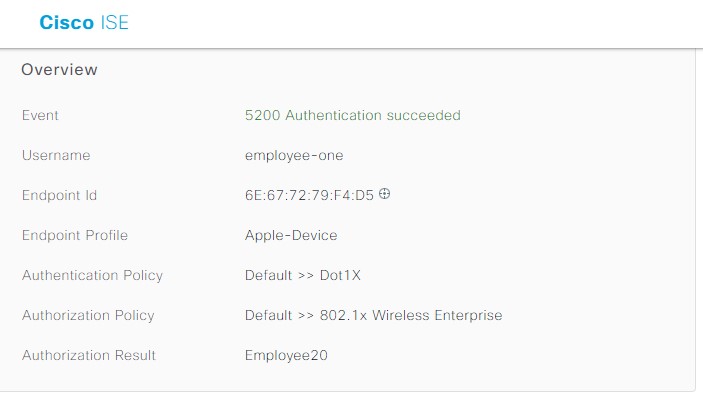
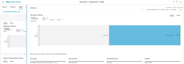
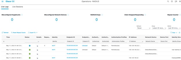
Operate the Wireless Network briefly discusses how Cisco DNA Assurance can be used to monitor and troubleshoot the WLAN deployment.
Topology
This content includes preconfigured users and components to illustrate the scripted scenarios and features of the solution. Most components are fully configurable with predefined administrative user accounts.
You can see the IP address and user account credentials to use to access a component by clicking the component icon in the Topology menu of your active session and in the scenario steps that require their use.
dCloud Topology
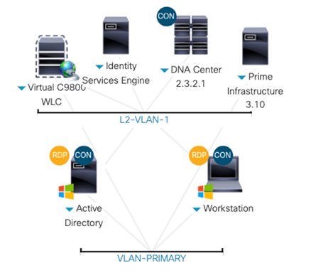
Table Server Details
| Device | IP Address | Access Method | Username | Password | Device |
|---|---|---|---|---|---|
| C9800-CL (17.8.1) |
Private: 100.64.0.7 |
Workstation1 Browser |
Session Owner | Session ID |
C9800-CL Bookmark |
|
Public: See Session Details |
Local Browser |
||||
| Workstation 1 |
198.18.133.36 NAT address: 198.18.128.250 |
Cisco AnyConnect RDP |
WIN10\Administrator | C1sco12345 | Workstation1 |
|
Active Directory (AD) |
198.18.133.1 |
RDP, VM Console |
DCLOUD\administrator |
C1sco12345 |
Automation (AD) |
| ISE (3.1 patch 3) |
100.64.0.100 NAT address: 198.18.128.100 |
Workstation1 Cisco AnyConnect, Local Browser, VM Console |
admin | C1sco12345 | ISE bookmark |
| Prime Infrastructure (3.10) | 198.18.136.100 | Workstation1 Browser | root | @Dm!n12345 | Cisco PI Bookmark |
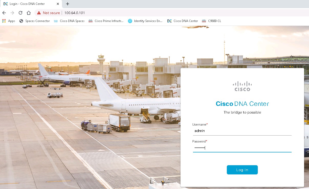
| DNA Center (2.3.2.1 Frey) |
100.64.0.101 NAT address: 198.18.128.101 |
Workstation1 Cisco AnyConnect, Local Browser, VM Console |
admin | C1sco12345 | DNA Center Bookmark |
Before You Present
Cisco dCloud strongly recommends that you perform the tasks in this document before presenting it in front of a live audience. This will allow you to become familiar with the structure of the document and content.
dCloud recommends using the Chrome browser for all demos.
PREPARATION IS KEY TO A SUCCESSFUL PRESENTATION.
Get Started
Follow these steps to schedule a session of the content and configure your presentation environment.
Procedure
| 1 |
Initiate your dCloud session. [Show Me How] Note: It may take up to 55 minutes –1 hour for your session to become active.
|
||||||
| 2 |
For best performance, connect to the workstation with Cisco AnyConnect VPN [Show Me How] and the local RDP client on your laptop. [Show Me How]
Note: You can also connect to the workstation using the Cisco dCloud Remote Desktop client. [Show Me How] The dCloud Remote Desktop client works best for accessing an active session with minimal interaction. However, many users
experience connection and performance issues with this method.
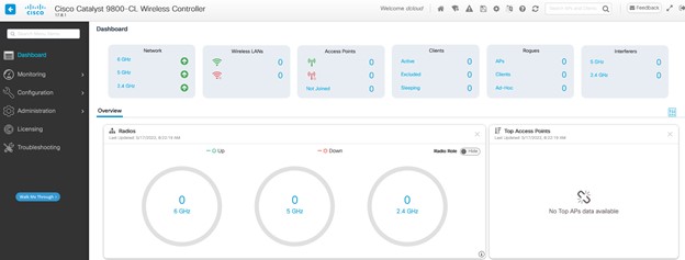
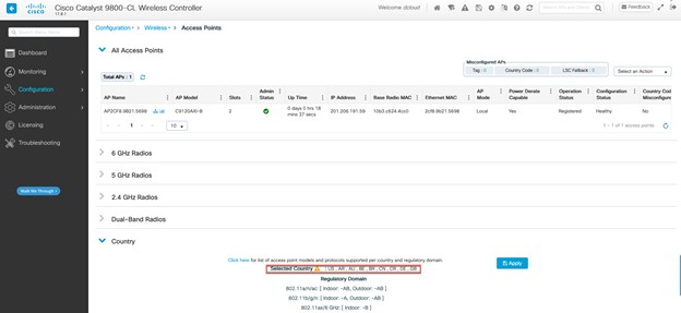
On Workstation1, ensure that your Country is enabled on the demo wireless controller (Cisco WLC). [Show Me How] Note: The Cisco WLC login for this demo requires session-specific credentials. The username is the name that you use to log in to
the dCloud UI and the password is the session ID. You can obtain this information in the session details section of your active
demo. The generic username of dcloud is also provided and can be used with the unique session ID as password, if necessary.
|
||||||
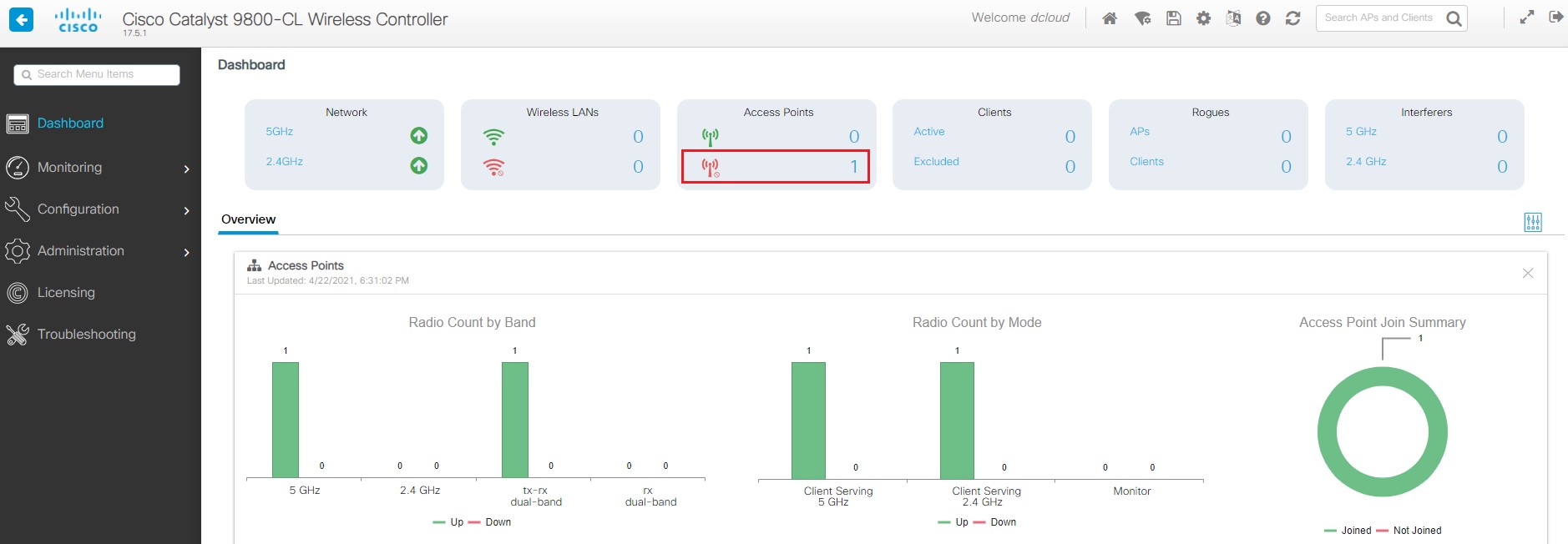
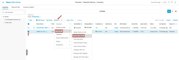
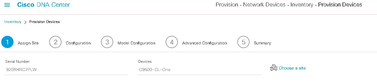
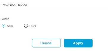
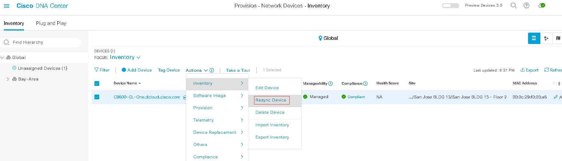
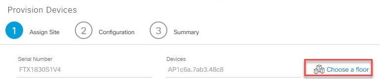
| 3 |
Provision your compatible AP. [Show Me How] Note: If you are using an endpoint router, this step only needs to be completed once. This is a HIGHLY recommended when using these
demos. Without an endpoint router, the AP must be re-provisioned with the new demo Cisco WLC IP address EACH time you schedule
a new demo.
|
||||||
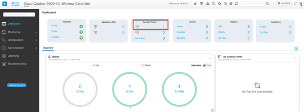
| 4 |
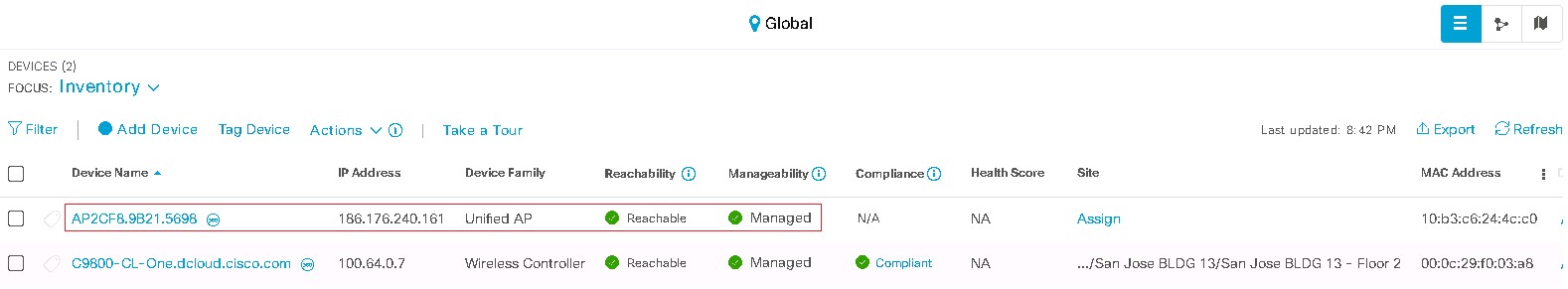
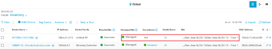
Verify your AP is operational. [Show Me How] You now have the option of connecting to Workstation1 through the AP. [Show Me How] |
||||||
| 5 |
You may need to complete other demonstration preparation activities, based on the location of your demonstration. Complete the additional demonstration preparation activities for demonstrating at a Cisco Office. [Show Me How] Complete the additional demonstration preparation activities for demonstrating at a Customer Site. [Show Me How] |